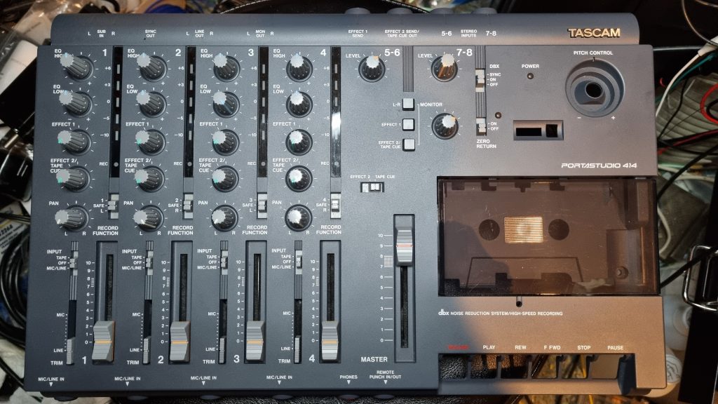
Another customer recommendation brought this unit in to see if an odd problem could be resolved – a ‘flubbing’ sound that occurs when armed for recording and levels above -10dB on meters. The unit was pristine, inside and out – looks like it had hardly been used.
At first the issue couldn’t be replicated – test signal and music recordings at various levels seemed to be fine – spent quite a while trying various things but couldn’t notice anything obvious.
Contacted the customer for more information, ask about grounding (was not the original linear psu) and even type of tape used and they reported that the noise seemed to occur on sharp attacks, like bass drum or a slap on a bass guitar.
That was critical information – armed with this, decided to look further and test with some pulse waveforms. Before this though, a short unterminated 1/4″ patch lead was connected to one of the inputs panned to LEFT and finger tapping the tip end to induce some short burst inductive 50Hz ‘body noise’ buzzing on a channel. Curiously, as the volume increased to where the -10 meter LED was just about lighting up, some faint buzzing noise could be heard in the RIGHT channel (but no right meter was lighting up)! This had to be an indicator of the fault surely as this didn’t seem right, there shouldn’t be any crosstalk with other inputs off!
If recording mode selectors were L or R rather than direct tracks, this noise would definitely be recorded to tape, which isn’t great (uncertain if direct 1/2/3/4 would be affected but suppose is possible).
As a matter of chance too, happened to play one of the previous recordings that was made with inputs set to TAPE, but with the channel volume sliders down, when some low frequency popping could be heard going on L-R outputs (master fader up and monitor volume up), and bingo – this was what the customer was reporting! It seemed every time one of the meter LEDs went ON or OFF, it would produce this noise. Explained the 50Hz buzzing too as the -10 LED was going on/off 50 times a second!
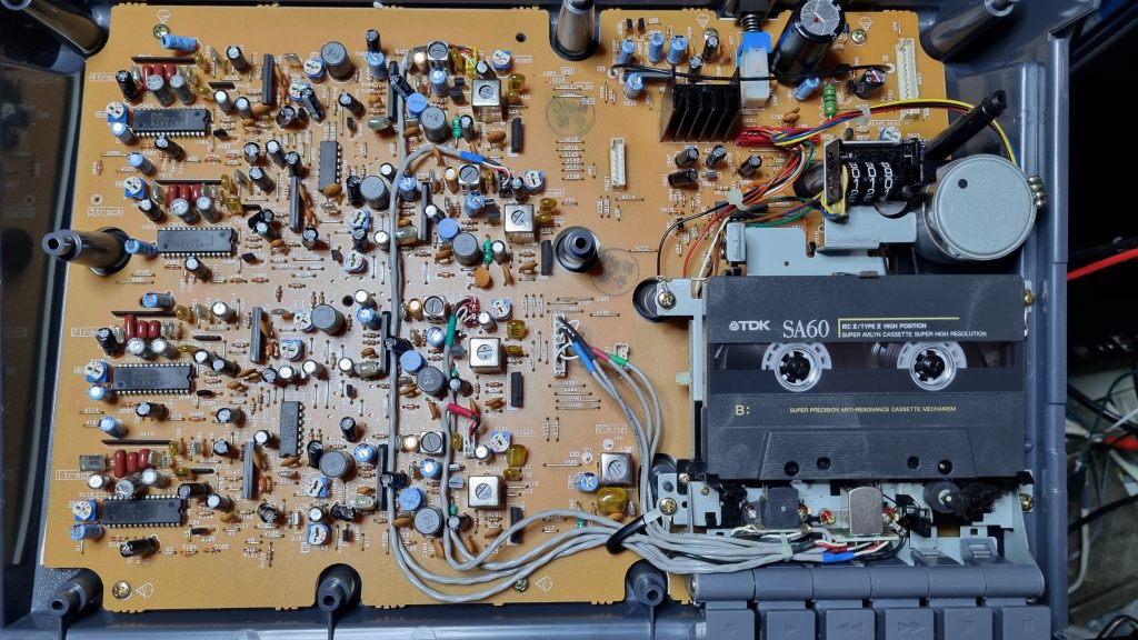
It was also noticed that when the mixer board section was moved about, a similar low ‘windy’ noise could be heard when the wires at the back right of the unit were moved (with pretty much max gain on master and monitor controls). Ahah! Bad grounding could cause this. Some continuity measurements were made but couldn’t see anything really bad so the top mixer section had to come off.
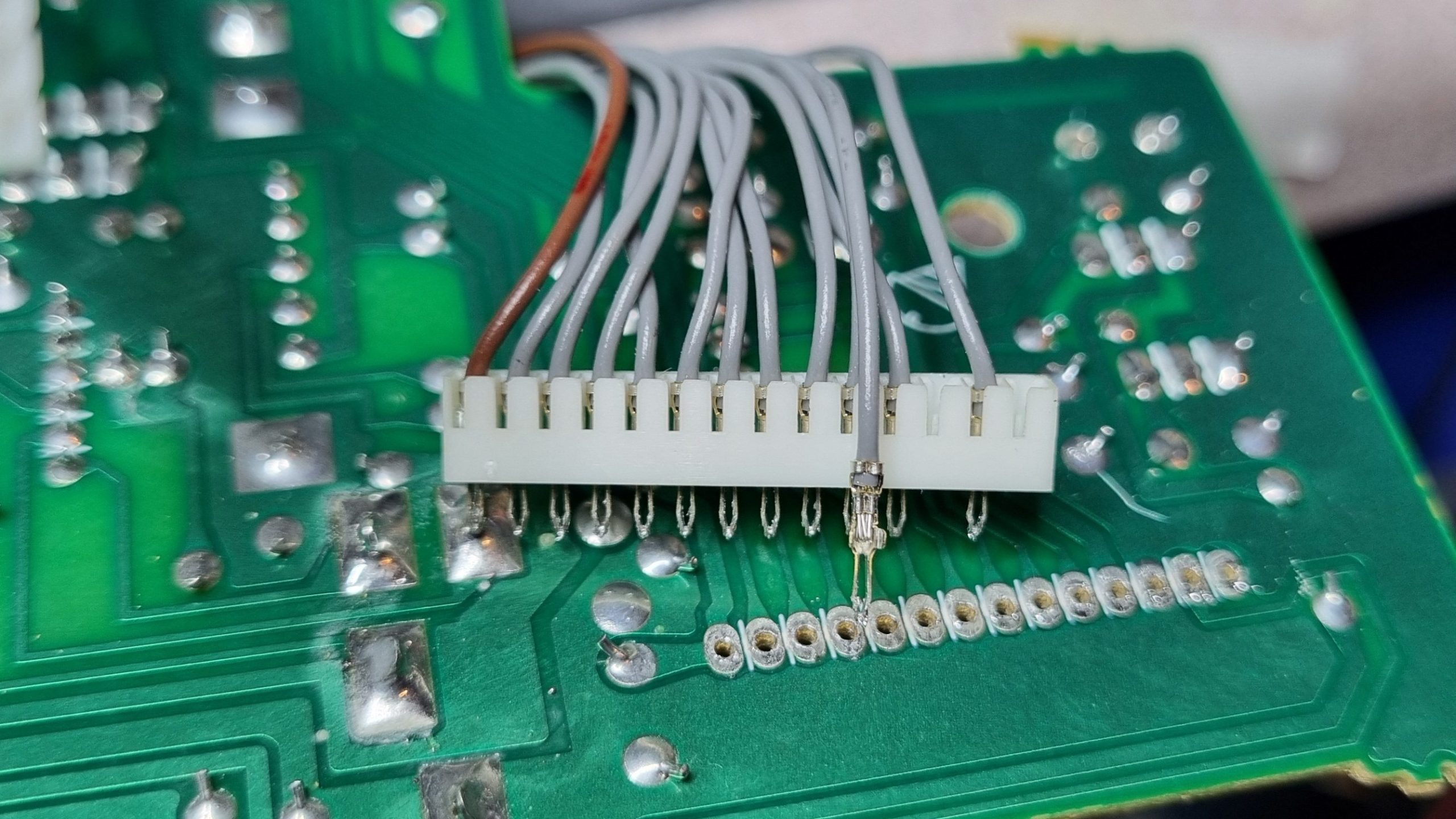
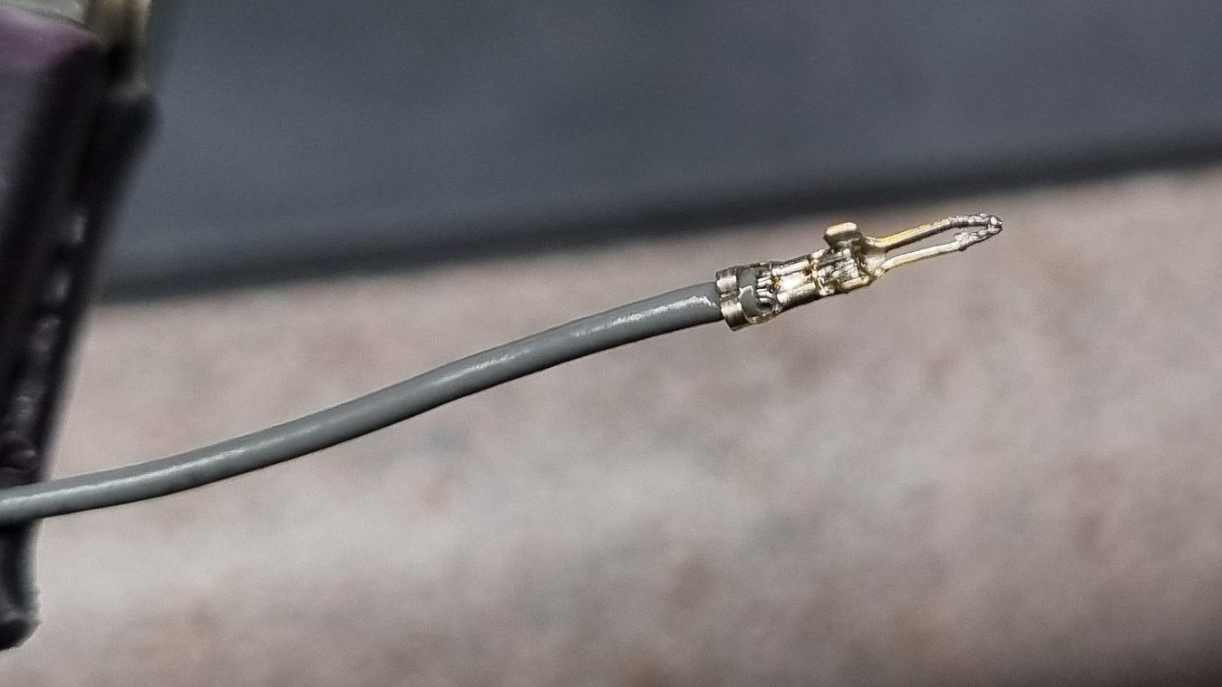
The cable pins and socket on the lower board was cleaned with deoxit, but this didn’t make much difference, however moving by hand the rightmost wires (GND and PWRONMUTE) the noise was still fairly noticable – it was suspected that perhaps the crimping had a bit of galvanic corrosion or similar (dissimilar metals reacting with each other over time).
So with this in hand, the pin header was desoldered from the mixer board, and the power pins were removed one by one, and soldered – both ends. That would eliminate any potential high resistance fault:
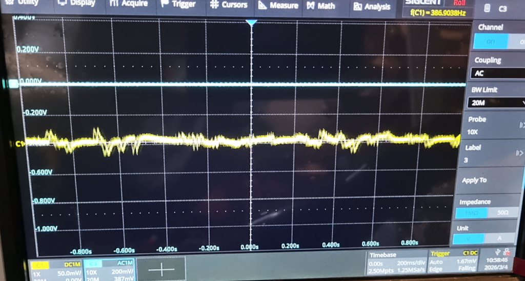
Unfortunately even after completing this fiddly operation, the issue still persisted! Each time an LED came on or off, a small bump could be seen and heard on the output.
Bumps on output manifesting themselves as a low frequency ‘pop’ – a bit like muffled pops heard in a microphone on a windy day (persistence on the scope roll mode creates a little shadow seen here in the trace, this isn’t part of the signal):
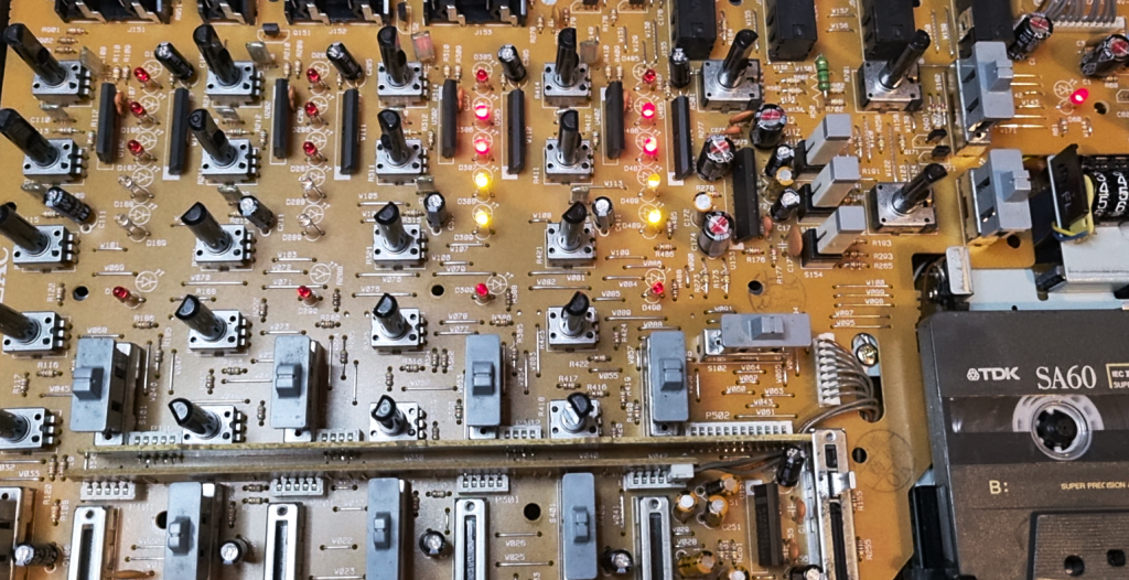
So now set about various means to solve. The device uses Sanyo LB1423N LED meter drivers, 9 pin SIL ICs and the datasheet says they’re ‘low noise’ for whatever that means. The audio inputs to these ICs are voltage divided and couldn’t see a path back to audio that way so the current drawn by the LEDs must be raising/lowering the ground potential and this is what was causing the noise in the audio output stages.
Adding extra ground straps made no difference. It was noticed that the LB1423N datasheet recommended 100R of resistance to the devices to limit current dissipation in the package when operated above 5V – these had their own supply at 9V derived from the main 9V supply with a power on delay. When 100R was added (used a 100R pot to test with various positions), the noise changed, became more higher frequency popping which was worse in a way, so looked for another solution.
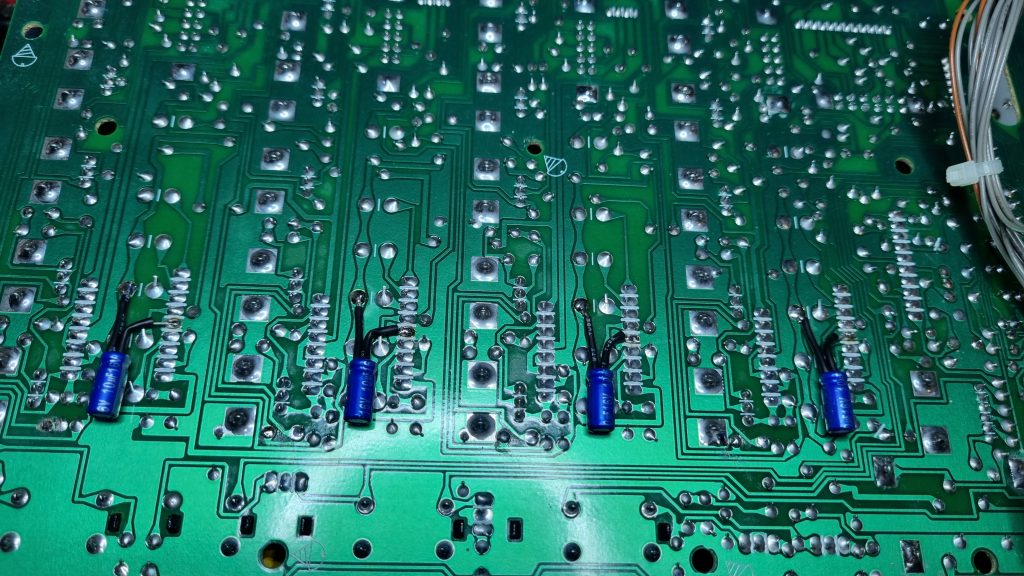
The LED ground paths did seem to be separated from the grounds on the channel op amps so TEAC did at least try optimising, however seemingly not enough. The 9v supply came via a 100uF Rubicon capacitor (all the caps were still in perfect condition, in fact better dissipation factor, ESR and capacitance than some of the newer stuff). However as a test it was swapped for a brand new Rubicon one, no difference – if anything was worse.
Then as a test swapped it out for a 1000uF cap. Instantly this made a difference, so thought was on the right track, the noise however attenuated, it was still a bit ‘there’. So decided to add 10uF caps at each meter IC to further decouple the supply – this improved things much further.
Then went back to the 100R resistor thought as another test, and with all THREE modifications performed, we were onto a winner! The noise was all but silenced – it could still be seen a little on the scope, but it no longer was audible. The only downside is that with the resistor, the meter LEDs could be a little dimmer when more were active, but felt this is an acceptable compromise.
Ok, so in an ideal world music would drown out such minor disturbances, but once someone hears this noise, they will be tuned into it. I suspect every 414 has this issue from factory, and it’s never really been noticed except in certain circumstances.
Customer happy to hear that the issue was found, and after explaining that the recorded levels between tracks was found to be a little imbalanced, accepted that a full service/calibration be performed, so this was done. Faders were ok but some noisy pots were treated with Deoxit F5.
Belts and deck mechanics were perfect, speed was confirmed to be accurate, as were playback levels, although azimuth needed a very slight tweak to bring all channels into phase.
Bias/erase frequency was spot on at 85Khz, the bias levels and the frequency response was good, but the ‘dbx Timing’ measurement (between R116/216/316/416 and GND) was off at 16.6mV so was brought up to the specified 18.4mV, and also as previously noticed, the recording levels were a little drifted, these were adjusted and playback of recorded material was then reflecting that of the input levels. A really nice unit, quite an achievement for compact cassette tape!
The customer should now have a regained confidence in their Tascam 414 and will no doubt enjoy continuing making some good recordings!